


A typical passive speaker system includes three important parts:
- The amplifier or receiver sends an audio signal through its speaker output.
- The speaker wire carries that signal to the speaker.
- The speaker driver converts the electrical signal into sound.
If any one of these parts fails, the speaker may stop working correctly.
A digital multimeter can help you troubleshoot the system by checking each part separately. You can use it to perform a basic electrical check on a passive speaker.
Understanding how to use a multimeter in this situation starts with knowing which part of the speaker system you are testing and choosing the correct meter setting for that test. This guide explains how to check each part safely and how to understand the readings on your multimeter.
What You'll Need:
-
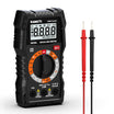
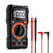
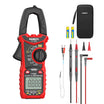
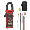
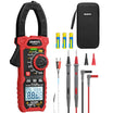
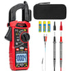
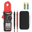
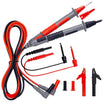
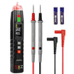
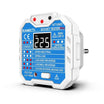
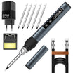
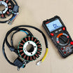
A Digital Multimeter
- Speaker
- Electrical tape
- Wire strippers
Safety Before Testing a Speaker System
Before using your multimeter, make sure you are testing the correct part of the system with the correct setting.
- Turn off the amplifier or receiver before disconnecting speakers or wires.
- Never use resistance mode or continuity mode on an energized circuit.
- Disconnect the speaker from the amplifier before measuring speaker resistance.
- Disconnect both ends of a speaker wire before checking continuity or shorts.
- When testing powered speaker output, keep the probes from touching each other or bridging the positive and negative terminals.
- Start output testing at a moderate volume level.
- For tube amplifiers or specialized audio equipment, follow the manufacturer’s instructions before operating the amplifier without its normal speaker load.
These precautions help protect both the multimeter and the audio equipment.
How to Test a Passive Speaker With a Multimeter
This test checks the electrical continuity of the speaker voice coil. It is most useful for passive speakers, car speaker drivers, woofers, or other speaker drivers with accessible terminals.
It can help identify an open or shorted voice coil, but it cannot fully confirm sound quality or overall speaker performance.
Step 1: Turn Off the Audio Equipment
Turn off the amplifier, receiver, or audio device before disconnecting the speaker.
Do not measure speaker resistance while the speaker is still connected to powered equipment.
Step 2: Disconnect the Speaker
Remove the speaker wires from the speaker terminals. The speaker should be electrically separated from the amplifier and wiring before you measure it.
If you are testing a removable speaker driver inside a larger speaker cabinet, follow the product instructions before removing or disconnecting the driver.
Step 3: Set the Multimeter to Resistance Mode
Turn the multimeter dial to the resistance setting, marked with the omega symbol: Ω.
If you are using a manual-ranging multimeter, select a low resistance range, such as 200 Ω. If your multimeter is auto-ranging, simply select resistance mode.
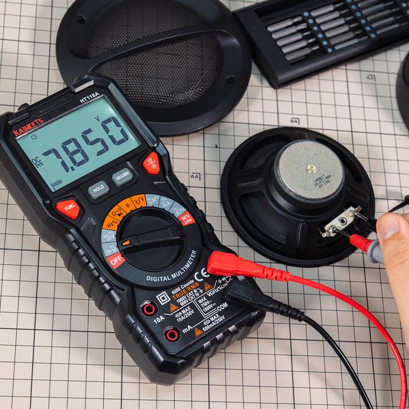
Step 4: Place the Probes on the Speaker Terminals
Touch one probe to each speaker terminal.
For a simple resistance measurement, it does not matter which probe touches the positive or negative terminal.
Step 5: Read the Resistance Value
A passive dynamic speaker or speaker driver will often show a finite, non-zero resistance reading when its voice coil has electrical continuity.
However, the value displayed on the multimeter is not the same as the speaker’s printed impedance rating.
A speaker may be labeled 4 Ω or 8 Ω, but that rating refers to its nominal impedance during operation with an audio signal. A multimeter measures DC resistance, which is often lower than the nominal impedance rating.
For many passive dynamic speaker drivers, example readings may look like this:
| Nominal Speaker Rating | Possible DC Resistance Reading |
|---|---|
| 4 Ω driver | Approximately 2 to 3.5 Ω |
| 8 Ω driver | Approximately 5 to 7 Ω |
| 16 Ω driver | Approximately 11 to 14 Ω |
These readings are examples, not universal limits. Speaker design, crossover networks, and manufacturer specifications can affect the measurement.
How to Understand the Speaker Reading
| Multimeter Reading | Possible Meaning |
|---|---|
| A finite, non-zero resistance reading | The voice coil has electrical continuity |
| OL, infinity, or a very high reading | The voice coil or connection may be open |
| A reading extremely close to 0 Ω | The voice coil may be shorted |
A normal resistance reading does not prove that the speaker will sound normal. A speaker may still have a damaged cone, rubbing voice coil, loose suspension, buzzing, or distortion that cannot be diagnosed with a basic resistance test.
How to Test Speaker Wire With a Multimeter
If the speaker itself shows a reasonable resistance reading but still does not produce sound, the speaker wire may be the problem.
Speaker wire usually contains two separate conductors: one positive and one negative. A multimeter can help you check whether either conductor is broken and whether the two conductors are accidentally shorted together.
Step 1: Turn Off the System and Disconnect the Wire
Turn off the amplifier or receiver.
Disconnect the speaker wire from both the speaker and the amplifier. Both ends of the cable should be disconnected before testing.
Step 2: Set the Multimeter to Continuity Mode
Set the multimeter to continuity mode. This setting is often shown with a buzzer or sound-wave symbol.
If your multimeter does not have a continuity setting, use the lowest resistance range instead.
Step 3: Check the Positive Conductor
Touch one probe to the positive conductor at one end of the speaker wire. Touch the other probe to the positive conductor at the opposite end.
If the meter beeps or shows very low resistance, that conductor has continuity.
If the meter shows OL, infinity, or very high resistance, the conductor may be broken or disconnected.
Step 4: Check the Negative Conductor
Repeat the same test on the negative conductor.
Both the positive and negative conductors need to have continuity for the speaker cable to carry the signal properly.
Step 5: Check for a Short Between the Conductors
With the cable still disconnected from all equipment, place one probe on the positive conductor and the other probe on the negative conductor.
| Test Result | Possible Meaning |
|---|---|
| No beep or OL | The two conductors are not shorted together |
| Beep or very low resistance | The two conductors may be touching or shorted |
A short may be caused by damaged insulation, loose wire strands, improper installation, or damage near the terminals.
How to Test Speaker Output With a Multimeter
If the passive speaker and speaker wire both appear normal, the next step is to check whether the amplifier or receiver is sending an audio signal to the speaker.
This is what speaker output testing means.
In this test, you are not measuring the resistance of the speaker. You are measuring the audio signal coming from the amplifier’s speaker output terminals.
Speaker Test vs. Speaker Output Test
| Test | What You Are Checking | Correct Meter Setting |
|---|---|---|
| Testing a disconnected passive speaker | The speaker voice coil | Resistance / Ω |
| Testing disconnected speaker wire | The cable connection | Continuity or Resistance / Ω |
| Testing active speaker output | The amplifier’s audio output signal | AC Voltage / V~ |
Do not use resistance mode or continuity mode on active speaker output terminals.
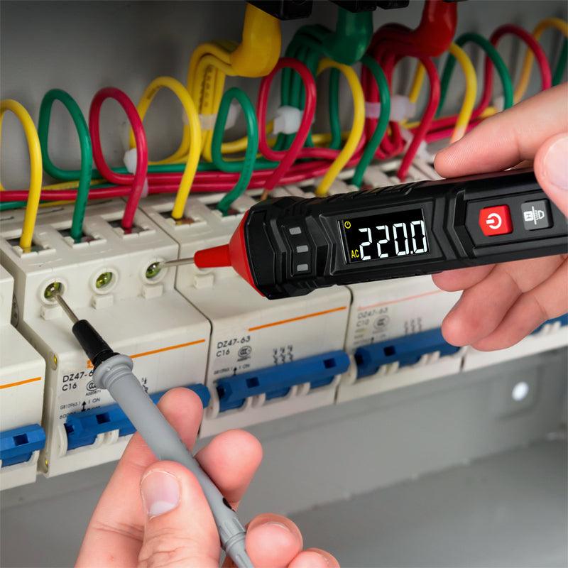
Step 1: Set the Multimeter to AC Voltage
Turn the multimeter dial to AC Voltage, usually shown as V~.
If the multimeter is manual-ranging, begin with a range above the expected output voltage. You can lower the range later when necessary for a clearer reading.
Step 2: Play a Steady Test Tone
Play a steady test tone through the amplifier or receiver.
For a regular full-range speaker channel, a test tone around 1 kHz can be used for a basic output check. A steady tone is easier to measure than music because music constantly changes in level and frequency.
Keep the volume at a moderate level during the initial test.
Step 3: Measure the Speaker Output Terminals
Carefully touch the red probe to the positive terminal of the output channel being tested and the black probe to the negative terminal of the same channel.
For example, when testing the right speaker output channel, both probes should be placed on the right channel output terminals.
Be careful not to allow the probe tips to touch each other while they are connected to the powered output terminals.
Step 4: Observe the AC Voltage Reading
With the test tone playing, the multimeter should display an AC voltage reading if the amplifier is producing output on that channel.
There is no single voltage reading that is normal for every speaker system. The measured voltage depends on:
- The amplifier power
- The volume level
- The test tone level
- The connected speaker load
- The audio system design
For troubleshooting, it is often more useful to compare two matching channels under the same conditions.
For example, if the left channel displays an AC voltage reading while the right channel stays at or near zero when tested with the same signal and volume setting, the right output channel may have a problem.
A multimeter can help confirm whether an output signal is present, but it does not provide a complete analysis of audio quality, distortion, clipping, or frequency performance.
Possible Causes of Speaker Problems
There are many potential causes of speaker problems, and most of them can be traced back to issues with the speaker itself, the audio source, or the connection between the two. Here are some of the most common causes of speaker problems:
Damaged Speakers:
If your speakers are damaged, they may not produce the sound correctly, or at all. Speaker damage can be caused by physical trauma (such as being dropped), water damage, or simply age and wear and tear.
Incorrect Speaker Connection:
If your speakers are not properly connected to the audio source, they may not produce sound. Make sure that the speaker cables are securely connected to both the speakers and the audio source.
Loose Speaker Cables:
If the speaker cables are loose, they may cause sound problems. Make sure that the cables are firmly connected at both ends.
Audio Source Problems:
If the audio source is not working correctly, it may be causing your speaker problems. Make sure that the audio source is turned on and functioning properly.
Incompatible Audio Source:
If the audio source is not compatible with the speakers, it may not work correctly. Make sure that the audio source and the speakers are compatible before using them together.
Dirty or Damaged Speaker Connections:
If the speaker connections are dirty or damaged, they may cause sound problems. Clean the connections with a clean, dry cloth, and make sure that they are free of dirt, dust, and other debris.
Low-Quality Audio Files:
If you are using low-quality audio files, they may not play correctly on your speakers. Use high-quality audio files to avoid this problem.
Interference from Other Devices:
If other devices are causing interference, it may affect the sound quality of your speakers. Move the speakers away from other electronic devices to reduce interference.
Frequently Asked Questions:
Can I use a multimeter to test the speaker wire?
Yes, you can use a multimeter to test the speaker wire. You will need to set the multimeter to the ohms setting and touch the probes to the ends of the speaker wire. If the wire is good, then the multimeter should read a low resistance. If the multimeter reads a high resistance, then the wire is most likely faulty and needs to be replaced.

How many volts should be at the speakers?
This is a difficult question to answer as it depends on the specific speakers in question and the particular application. In general, however, most speakers will operate within a voltage range of around 5-12 volts. The specific requirements will be listed in the speaker's documentation. If you are unsure, it is always best to consult with a qualified professional to ensure that your speakers are getting the correct voltage.
Should I Use AC or DC Voltage to Test Speaker Output?
Use AC Voltage when checking whether an amplifier or receiver is sending an audio output signal to a speaker channel.
Use Resistance / Ω only when testing a disconnected passive speaker or speaker driver.
Conclusion:
In conclusion, testing your speaker with a multimeter is a quick and easy way to ensure that your speakers are functioning properly. By following the steps outlined in this article, you can easily test your speaker wire and confirm that your speakers are receiving the proper signal. Additionally, testing the resistance of your speaker wire can also help you determine if there are any breaks or shorts in the wire. By testing your speaker output regularly, you can ensure that your audio system is always performing at its best.


Leave a comment
All comments are moderated before being published.
This site is protected by hCaptcha and the hCaptcha Privacy Policy and Terms of Service apply.