




















Line and load describe the direction of power at a specific electrical device. The line side receives power from the upstream source. The load side sends power to a light, receptacle, or another downstream device.
Correct identification is important when installing a GFCI receptacle or smart switch. Reversing the connections may prevent the device from working. It can also stop downstream protection from operating as intended.
Identifying line and load conductors may require voltage testing near exposed wiring. This is hazardous. If you are not trained and equipped to perform energized testing, stop and contact a licensed electrician.
What is the difference between line and load wires?
The line side brings power into a device, while the load side carries power away from it.
Line and load are circuit roles rather than fixed wire types. A black conductor may be the incoming line at one device and the outgoing load at another point in the circuit.
The meaning also depends on the device:
- At a GFCI receptacle, LINE is the incoming supply cable. LOAD feeds optional downstream receptacles that will also receive GFCI protection.
- At a light switch, line usually means the constant hot conductor. Load usually means the switched conductor going to the light.
- At a standard duplex receptacle, electricians may use “line side” and “load side” to describe upstream and downstream cables. The receptacle may not have separate LINE and LOAD terminals.
A load conductor is not necessarily safe to touch. It can become energized when the switch or upstream device supplies power to it.
What tools do you need to identify line and load wires?
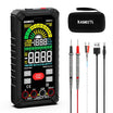
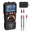
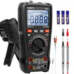
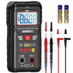
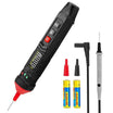
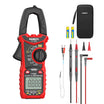
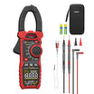
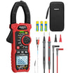
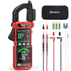
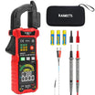
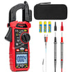
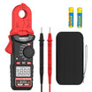
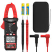
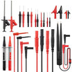
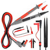
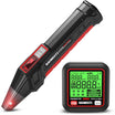
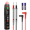
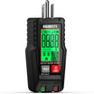
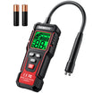
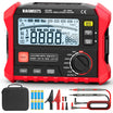
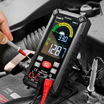
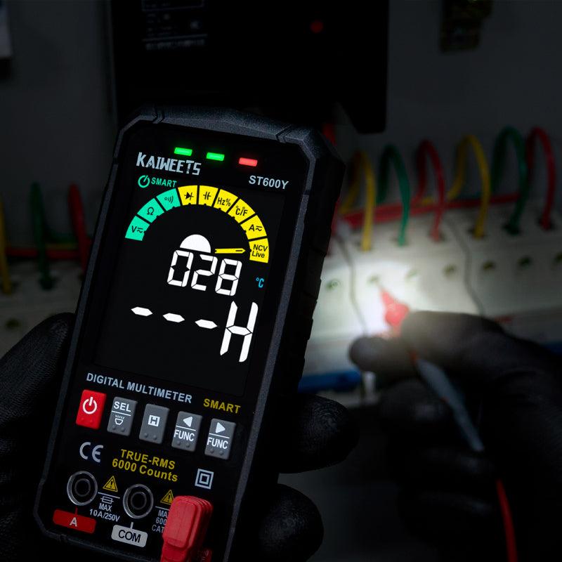
A properly rated multimeter is the most reliable tool for confirming which cable supplies voltage.
- A multimeter measures the actual AC voltage between two conductors.
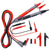
- Use intact test leads with insulated probe guards. The meter and leads must have ratings suitable for the circuit being tested.
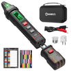
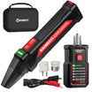
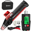
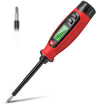
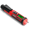
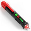
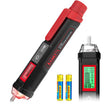
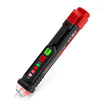
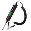
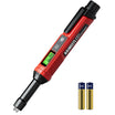
- A non-contact voltage tester is useful for an initial voltage check. It should not be the only tool used to prove that wiring is de-energized.
- Use approved wire connectors to isolate disconnected conductors. Labels or tape can help you mark the confirmed line cable.

How do you identify line and load wires safely?
The safest reliable method is to isolate the conductors and measure which cable still receives voltage from the electrical panel.
Professional electrical safety practice is to de-energize exposed conductors before working on them. Only qualified people should perform tests that require an open electrical box to be energized.
Before you begin
Confirm that the wiring arrangement is simple enough to identify safely before disconnecting anything.
Stop and contact an electrician when the box contains any of the following:
- Conductors supplied by more than one circuit
- A shared neutral or multi-wire branch circuit
- Three-way or four-way switch wiring that you cannot positively identify
- Damaged insulation, overheating, or loose connections
Keep in mind that switching off one breaker may not de-energize every conductor in a multi-gang box.
Method 1: Identify line and load wires with a multimeter
A multimeter provides the clearest result because it measures the voltage present on each isolated cable.

- Turn off the circuit breaker. Confirm that the connected light or receptacle has lost power.
- Inspect the test equipment. Check the meter body and test leads for visible damage. Set the meter to AC voltage.
- Verify that the meter works. Test it on a known live voltage source before checking the de-energized circuit.
- Confirm the box is de-energized. Test between the suspected hot and neutral conductors. Test hot to ground where an intact equipment ground is known to be present.
- Document the existing wiring. Take a clear photo before removing the device. Do not rely on memory alone.
- Separate the cables. Disconnect the conductors only after confirming the power is off. Cap each exposed conductor separately with an approved connector.
- Restore power only for the voltage test. Keep the conductors separated. Do not touch the box or exposed metal.
- Measure one cable at a time. Place one probe on the suspected hot conductor. Place the other probe on the corresponding neutral conductor.
- Identify the incoming supply. The cable that shows the circuit’s nominal voltage is the line cable.
- Turn the breaker off again. Verify that voltage is absent before labeling or reconnecting the conductors.
- Reconnect the device. Follow its wiring diagram and terminal markings. Restore power only after the device is secured in the box.
On a typical North American 120-volt branch circuit, the incoming line will usually measure close to 120 volts from hot to neutral. The expected reading will be different in countries that use another nominal supply voltage.
A conductor may show no voltage because it is disconnected, abandoned, switched off, or part of another wiring arrangement. Confirm its destination before reconnecting it as a load.
Method 2: Check terminal markings and manufacturer instructions
Terminal labels can confirm where a verified line or load cable should be connected.
GFCI receptacles normally have separate LINE and LOAD terminals. The incoming supply must connect to LINE. The LOAD terminals are used only when you want the GFCI to protect downstream receptacles.
Many GFCI models are shipped with a sticker covering the LOAD terminals. Leave the sticker in place when no downstream protection is required.
Labels do not identify the cables by themselves. You must first determine which cable is the incoming source.
Method 3: Trace the circuit position
Cable position can provide a useful clue, but it is not a dependable substitute for electrical testing.
The line cable normally comes from the panel or another upstream device. A load cable continues toward a light or downstream receptacle.
Physical direction inside the box may be misleading. Cables can enter from any side, and previous work may not follow an obvious route.
Can wire color identify line and load?
No. Wire color may indicate a conductor’s usual function, but it cannot reliably tell you whether the conductor is line or load.
In common North American wiring, black or red insulation often identifies an ungrounded hot conductor. White is normally used for neutral, while bare copper or green is normally used for equipment grounding.
Both an incoming line conductor and an outgoing load conductor may be black. A switched load can also be red.
Older wiring may use faded insulation. A white conductor may also have been reidentified for another purpose in certain switch configurations. Always verify the function with an appropriate test instrument.
How do line and load connections differ by device?
Line and load have the same general meaning, but the exact wiring arrangement depends on the device being installed.
GFCI receptacles
On a GFCI receptacle, LINE powers the GFCI itself. LOAD supplies optional downstream outlets that will be protected when the GFCI trips.
Connecting the incoming supply to LOAD instead of LINE can prevent many modern GFCIs from resetting. The receptacle may also remain without power.
After installation, use the TEST and RESET buttons. Confirm that every downstream receptacle connected to LOAD loses power when the GFCI is tested.
Standard and smart switches
At a switch, line is usually the unswitched hot conductor and load is the switched output going to the fixture.
A standard mechanical switch may connect only line and load. Many smart switches also require a neutral connection for continuous electronic power, although some models are designed to work without one.
Three-way and four-way circuits also contain traveler conductors. Those wires should not be classified by using a simple line-versus-load test alone.
Standard duplex receptacles
A standard receptacle often has internally connected terminal pairs rather than dedicated GFCI-style LINE and LOAD terminals.
One cable may bring power into the box while another continues downstream. Once connected to the receptacle, both hot conductors are normally energized unless a connecting tab has been removed for a special circuit arrangement.
What are the most common questions about line and load wires?
The most common questions concern voltage readings and wire color. The limits of different testing tools also matter.
Is the load wire always dead?
No. A load conductor can become energized whenever the upstream device supplies power to it. For example, a switched load becomes energized when the switch is turned on.
Can a non-contact voltage tester identify line and load wires?
A non-contact tester can help locate possible energized conductors, but it cannot reliably confirm line and load by itself. Nearby wires may produce misleading indications.
Use a properly rated contact meter when an exact voltage measurement is required. Follow the tester manufacturer’s instructions.
What voltage should the line wire show?
The line cable should show approximately the nominal supply voltage for the circuit. A common U.S. household branch circuit will usually read near 120 volts from hot to neutral.
A lower or unstable reading may indicate a wiring problem. It may also be caused by a high-impedance or induced voltage. Do not reconnect the circuit until the result is understood.
What happens if LINE and LOAD are reversed on a GFCI?
Many modern GFCI receptacles include line-load reversal protection. A miswired device may not reset or provide power.
Behavior can vary by model. Always use the terminal labels and installation diagram supplied with the specific GFCI.
Can I identify line and load wires without turning the power on?
Sometimes. An electrician may trace disconnected cables with a continuity tester or circuit tracer while the circuit is de-energized.
Continuity testing must never be performed on an energized circuit. All connected loads should also be isolated so they do not affect the reading.
Conclusion
Line is the upstream power source at a device, while load carries power to the next part of the circuit. The most dependable identification method is a controlled voltage test with the conductors safely isolated.
Do not identify wiring by color or cable position alone. Turn the breaker off before handling conductors, verify that voltage is absent, and follow the device manufacturer’s diagram.
If the box contains unfamiliar wiring or more than one circuit, use a licensed electrician. This is especially important for shared neutrals and multi-way switches.
If you’re updating multiple outlets or switches, our guide to GFCI vs Circuit Breaker: Understanding the Difference explains how these devices provide different types of electrical protection.
Technical safety guidance: OSHA electrical work practices and ESFI DIY electrical safety guidance.
Testing and installation references: Leviton GFCI installation instructions.


1 comment
John Baughman
I have a 4 way switch set up in my room. I want to replace the three switches with a Caseta wireless system that uses two wireless remotes in place of wired switches. I can easily distinguish between the two 3 way switches and the one 4 way switch. However, since only one switch is to be connected to the house wiring, I’m having trouble understanding where the new smart switch should be installed. In place of one of the 3 way switches or in place of the 4 way switch. Thanks for your advice.
Leave a comment
All comments are moderated before being published.
This site is protected by hCaptcha and the hCaptcha Privacy Policy and Terms of Service apply.