


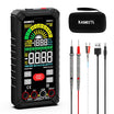
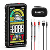
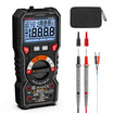
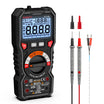
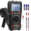

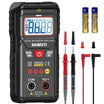
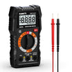
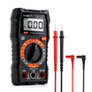
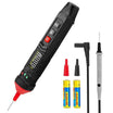
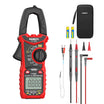
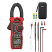
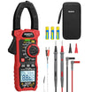
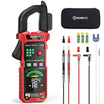
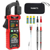
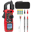
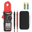
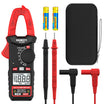






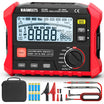















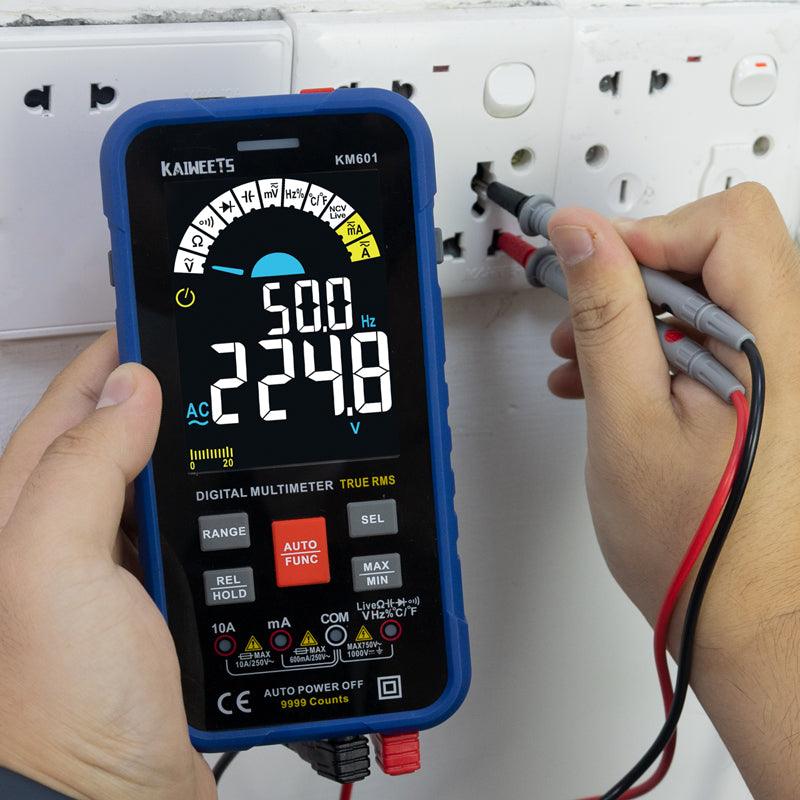
Duty cycle tells you how much of each signal period is ON. If your digital multimeter has a Hz/% function, it can usually measure duty cycle directly on many square-wave or PWM signals.
This is different from measuring AC or DC voltage. A duty-cycle reading is about timing, not just voltage level. For quick troubleshooting, a multimeter can be very useful. For detailed waveform shape, an oscilloscope is still the better tool.

What Is Duty Cycle?
Duty cycle is the percentage of one complete cycle that a signal stays in its active state. In most PWM circuits, the active state means the high part of the pulse.
The basic formula is:
Duty cycle (%) = (ON time ÷ total period) × 100
For example, if a signal is ON for 2 milliseconds during a 10-millisecond period, the duty cycle is 20%.
A 50% duty cycle means the signal is ON for half of each cycle. A 100% duty cycle means the signal stays active all the time.
Can Any Digital Multimeter Measure Duty Cycle?
No. A digital multimeter must have a frequency or duty-cycle function to measure duty cycle directly.
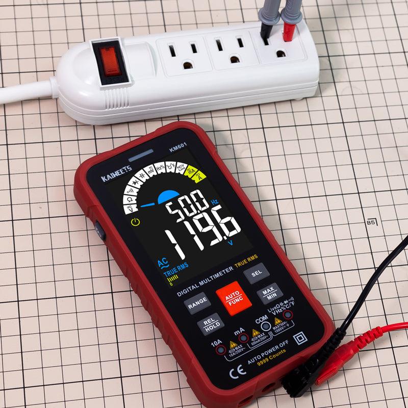
On many meters, this function is marked as Hz, %, or Hz%. Some meters require you to press a secondary function button after selecting frequency mode. A basic meter that only measures voltage, resistance, and current may not support duty-cycle readings.
Handheld multimeters are common for field checks because they are portable. Benchtop meters may offer higher accuracy, but they are less convenient for quick troubleshooting.
What Should You Check Before Measuring Duty Cycle?
Before measuring duty cycle, confirm that the signal is safe for the meter and suitable for the meter’s frequency range. The same basic habits covered in this guide on how to use a multimeter also apply here: use the correct input jack, choose the right mode, and stay within the meter’s rated limits.
- Meter function: Make sure the meter has a Hz/% or duty-cycle mode.
- Input jack: Use the voltage or frequency input jack, not the current jack.
- Signal type: Duty cycle is most useful for square-wave and PWM signals.
- Voltage level: Stay within the meter’s rated input limit.
- Frequency range: Check the manual if the reading is unstable or missing.
Do not probe a live high-energy circuit unless you are trained to do so and your meter, probes, and test method are properly rated for the job.
How Do You Measure Duty Cycle With a Digital Multimeter?
You measure duty cycle by selecting the meter’s Hz/% mode, connecting the leads to the signal and reference point, and reading the percentage on the display.
- Insert the black test lead into the COM jack.
- Insert the red test lead into the VΩ or Hz input jack.
- Turn the dial to the frequency setting.
- Press the function button until the display shows % if your meter requires it.
- Connect the black probe to circuit ground or the reference point.
- Connect the red probe to the signal output.
- Power the circuit and let the signal run normally.
- Read the duty-cycle percentage on the display.
If the number jumps around, check the probe connection first. A noisy signal, weak pulse, or wrong reference point can also cause unstable readings.
How Do You Calculate Duty Cycle Manually?
You calculate duty cycle by dividing the ON time by the total period, then multiplying the result by 100.
Duty cycle (%) = (pulse width ÷ period) × 100
Pulse width is the active time of the pulse. Period is the time for one complete cycle.
For example, a signal with a 5 ms ON time and a 20 ms period has a 25% duty cycle.
(5 ms ÷ 20 ms) × 100 = 25%
This method is easy if you already know the timing values. In real troubleshooting, a multimeter with duty-cycle mode or an oscilloscope is usually faster.
Can You Calculate Duty Cycle From Voltage?
You should not calculate duty cycle from voltage unless the waveform and voltage levels are clearly known.
For an ideal PWM signal with a known low level and high level, average voltage can give a rough duty-cycle estimate. In that case, the relationship is:
Duty cycle (%) = [(average voltage − low voltage) ÷ (high voltage − low voltage)] × 100
For example, if a 5 V PWM signal switches between 0 V and 5 V, an average voltage near 2.5 V suggests about 50% duty cycle.
This shortcut can be misleading on real circuits. Filtering, noise, meter response, and non-square waveforms can all affect the voltage reading. When accuracy matters, use the meter’s duty-cycle function or check the signal on an oscilloscope.
What Determines Duty Cycle?
Duty cycle is determined by the active pulse width compared with the total period.
| Factor | How It Affects Duty Cycle |
|---|---|
| Pulse width | A longer ON time increases duty cycle if the period stays the same. |
| Period | A longer period lowers duty cycle if the ON time stays the same. |
| Frequency | Frequency alone does not set duty cycle. It only tells you how often the cycle repeats. |
| Amplitude | Amplitude does not define duty cycle, but it can affect whether the meter detects the signal. |
This is why the original signal timing matters more than the voltage height when you are discussing duty cycle.
What Is the Difference Between Duty Cycle, Frequency, and Pulse Width?
Duty cycle, frequency, and pulse width describe different parts of the same repeating signal.
| Term | Meaning | Example |
|---|---|---|
| Duty cycle | The percentage of one cycle that is active. | 40% |
| Pulse width | The amount of time the signal stays active in one cycle. | 4 ms |
| Frequency | The number of cycles per second. | 250 Hz |
| Period | The time needed for one complete cycle. | 4 ms |
A signal can have the same duty cycle at different frequencies. For example, a 50% duty cycle simply means equal ON and OFF time within each cycle.
Where Is Duty Cycle Used?
Duty cycle is commonly used when a circuit controls average output by switching quickly.
- Motor speed control: A higher duty cycle usually sends more average power to the motor.
- LED dimming: A lower duty cycle can make the light appear dimmer.
- Control signals: Some sensors and modules use pulse timing to send information.
In these cases, the circuit may switch fully ON and OFF very fast. The connected load responds to the average effect.
Why Is My Duty-Cycle Reading Wrong or Unstable?
A wrong duty-cycle reading usually comes from the wrong meter setting, a weak signal, or a signal that is outside the meter’s measurement range.
| Problem | Likely Cause | What to Try |
|---|---|---|
| The meter shows voltage instead of %. | The meter is not in duty-cycle mode. | Select Hz/% mode or press the secondary function button. |
| The reading jumps around. | The signal is noisy or the probe contact is poor. | Check the ground point and use a steadier connection. |
| The display shows no reading. | The frequency or voltage may be outside the meter’s range. | Check the meter manual and signal level. |
| The value looks inverted. | The circuit may use an active-low signal. | Confirm whether the pulse is active high or active low. |
| The number does not match the circuit behavior. | The waveform may not be a clean square wave. | Use an oscilloscope to see the actual waveform. |
When Should You Use an Oscilloscope Instead?
You should use an oscilloscope when you need to see the actual waveform, not just a single duty-cycle number.
A multimeter is useful for quick checks. It can tell you whether a PWM signal is present and whether the duty cycle is roughly changing as expected.
An oscilloscope is better when the signal has ringing, slow edges, dropouts, or noise. It also helps when you need to confirm rise time, fall time, pulse width, or exact timing.
Frequently Asked Questions
How do you determine duty cycle?
You determine duty cycle by comparing the ON time with the total cycle time. Divide the ON time by the period, then multiply by 100.
Duty cycle (%) = (ON time ÷ total period) × 100
Is duty cycle the same as frequency?
No. Frequency tells you how many cycles happen per second, while duty cycle tells you how much of each cycle is active.
A 100 Hz signal and a 1 kHz signal can both have a 50% duty cycle.
Can a multimeter measure PWM duty cycle?
Yes, a multimeter can measure PWM duty cycle if it has a duty-cycle function and the PWM signal is within the meter’s supported range.
If the PWM signal is very fast, very weak, or heavily distorted, the reading may not be reliable.
Why does duty cycle matter?
Duty cycle matters because it affects how much average power or control action a switching signal delivers.
In a PWM motor circuit, for example, a higher duty cycle usually means more average power is applied to the motor.
What does a 50% duty cycle mean?
A 50% duty cycle means the signal is active for half of each cycle and inactive for the other half.
For a clean square wave, this produces equal high and low time.

Dig deeper:

Dejar un comentario
Todos los comentarios se revisan antes de su publicación.
Este sitio está protegido por hCaptcha y se aplican la Política de privacidad de hCaptcha y los Términos del servicio.